26 Mai

Cascade Filling

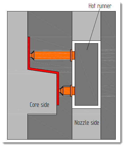
Multiple Nozzles for One Injection Molded Part

This variant, also called cascade injection molding,

is the classic version of multiple connections. Large

and extremely long parts, such as automobile bumpers,

are molded with multiple nozzles. Even parts

with different levels, such as garden chairs, are

molded with different lengths of hot runner nozzles.

This process is preferably used when no clamping

force reserve is present on the part of the injection

molding machine (see Section 6.9 Cascade Injection).

Multiple Nozzles for Multiple Injection Molded

Parts

When using multiple nozzles for multiple molded

parts, it is important that the flow paths from the

hot runner to the distributor are approximately the

same length in all nozzles to prevent a nonuniform

filling.

Hot runner

Core side

Nozzle


23 Mai

Tempering or Cooling Systems


1

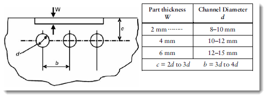
The cooling system by drilled holes  is located across the view of the image.

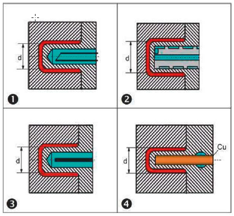
 2  In order to get efficient cooling of the core in the cavity, so-called facing cooling baffles are used.


Function:

  • to quickly get the correct mold temperature at the start-up or after an interruption in the production
  • uniform and rapid (economic)  cooling of the melt

  • The system should have sufficient capacity to provide a minimal temperature variation of the mold during
    • the work cycle of the machine or
    • the room temperature variations over the day or season of the year.

Mold Temperature is very important process parameter:

  • Cooling determines cycle time
  •  Affects part quality:
1

 Surface finish

 2   Strength and structure of the material
3  Dimensions (shrinkage)
4  Tendency to warp
5  Filling ratio
6  The strength of the weld lines


Risk:

  • Unsufficient Cooling/Temperature affects part quality (see table above)


Design:


Cavity Cooling:

  • All cavity inserts as well as the sliders and splits have to be cooled “directly”, which means touched and wetted by the cooling medium
  • cooling water flow in the same direction as the mass which flows into the cavity
  • avoid indirect heat transfer
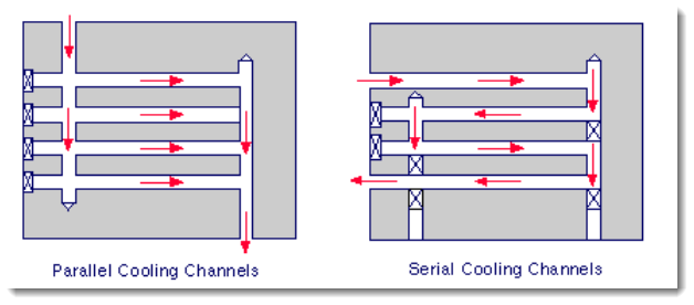
  • parallel connections preferred:
  • All circuits are fed by a common supply at a similar temperature
  • There is a lower temperature differential across the mould.
  •  There is a lower pressure drop between inlet and outlet.
  •  The mould temperature is more uniform.
  •  Circuit blockages are less easily detected.


  • cooling has to be incuded in Mold-Fill Simulations
  • recommended Mold temperature is given by resin supplier


Core Cooling:

1  cooling pipe
 2   spiral cooling
3   cooling baffle
4  cooling pins made of copper

Temperature Control units:

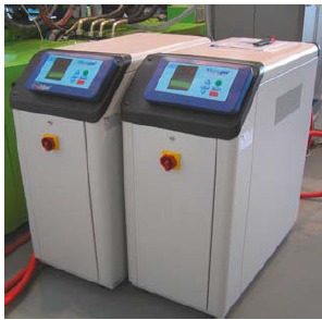
  • external temperature-control units
  • central tempering system for the entire production hall

  • one unit for each mold half or tempering circuit
  • Cooling medium is Water or for higher temperatures than 95 deg Celsius oil


Mold temperatures:


Cooling medium working range:


Conductivity of mold materials:


23 Mai

Venting Systems


1

 narrow slot leading from the cavity

2  venting channel
3  ejector pin with ground venting grooves that also lead directly out of the plate 


Function:

When filling a mold with a plastic melt, the entrapped air in the runners and cavities must get a chance to get out.

In order to do this you have to build in air vents at the spots where the air otherwise would have been trapped.


Risk:

  •  If the venting is inadequate there is a risk of filling problems of the cavities.
  • Surface burns may also occur on the parts where the compressed air is trapped.
  • reduce physical properties at weld lines

Design: