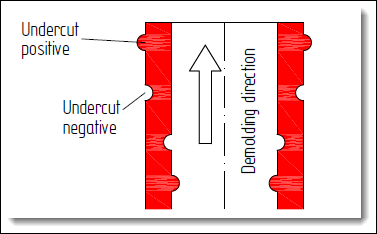
- positive or negative change in the geometry at the inner or outer diameter is called an undercut.
- Parts with internal undercuts are fundamentally harder to demold
Design:
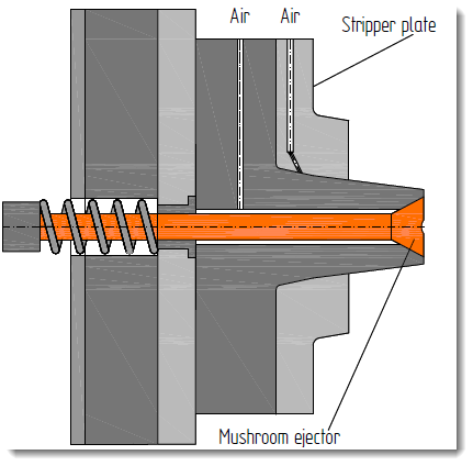
Elastic Stripping:
- molded part is demolded by a simple stripping during opening of the mold without a slider.
- works with tough and elastic materials :
- polypropylene (PP),
- polyethylene (PE),
- soft polyvinyl
- chloride (PVC),
- or elastomers.
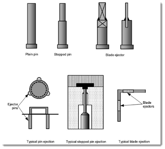
- frequently used ejector features are stripper plates.
- Ejector pins, push-out sleeves, or air may also be used.
Applications: screw caps. medical and packaging area
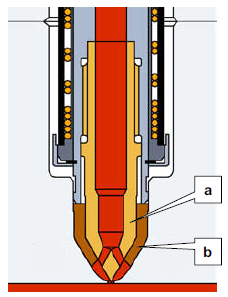
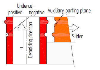
Demolding through Sliders:
- Auxiliary parting planes can be generated with sliders to release partial molded part areas that have an undercut
- Sliders location either into the nozzle or ejector side
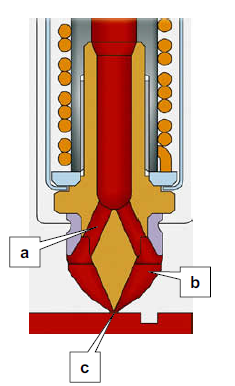
- At mold opening the slider runs to the side of the mold axis at an angle of 90°.
- A maximum deviation of 7° in both directions should not be exceeded otherwise the slider could lock.
-
The movement of the slider is carried out mechanically by a sloping or control bolt, also called the positive control.
movement of the slider can take place before, during, or after the opening of the mold,
-
Actuator: springs, air, or hydraulic cylinders.
-
applications:
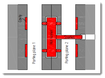
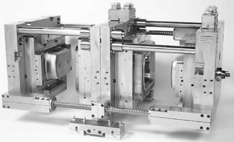
Demolding with Jaws (Split Molds):
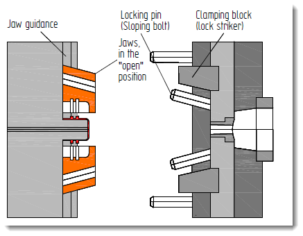
- two or more jaws completely enclose the molded part and form the mold cavity. T
- Actuated mostly with hydraulic cylinders or mechanically using springs
- Jaws should beintegrated into the cooling circuits of the molds.
- Split molds can be combined with all known
- manifold systems and gate variations.
- applications: bottle crates and car batteries.
Collapsible Cores:

diameter : 15 mm < d < 500 mm
Applications: thread or thread-like undercut on covers used for resealable containers
Demolding Internal Thread:
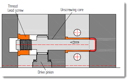
- demolding by rotation of the threaded cores
- mold part must be secured against rotation:
Unscrewing when the Mold is Closed:
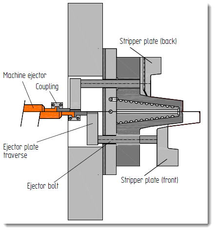
Unscrewing for an Attached Stripper Plate:
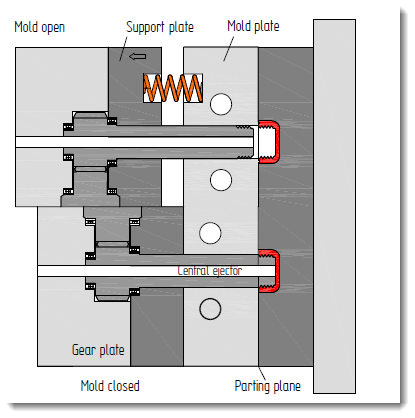
- stripper plate is attached to the nozzle side
- rotating cores are not retracted
- machine opens parallel to the thread pitch
- stripper plate is pressed against the nozzle side with spring force.
- The injection molding machine drives up
- parts are ejected by the stripper plate
Advantage:
- No expensive design of the threaded cores or expensive lead screws are required.
- No loss of time occurs by turning back the threaded cores.
Disadvantage:
- A portion of the closing force is lost by the counter force of the springs.
Unscrewing the Stripper Plate with Spring Force:
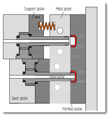
cores do not run back but pressed back with the spring force of the support plate
molded thread in the injection molded part takes over the task of the lead screw
molded thread is strongly loaded.
danger, that the last gear can be damaged
Advantage:
- manufacture is cost-efficient
Disadvantage:
- thread is of lower quality.