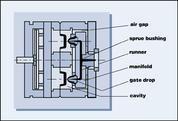
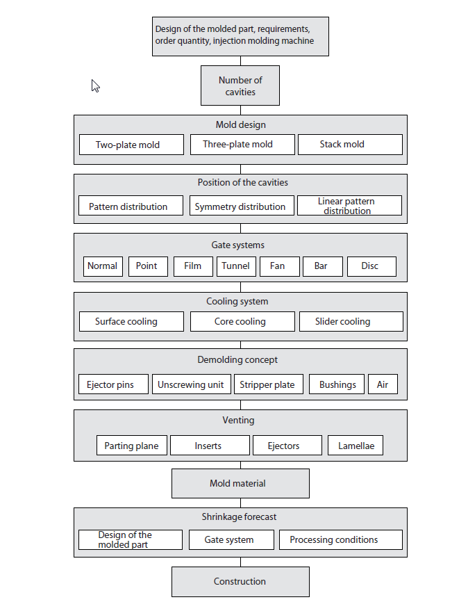
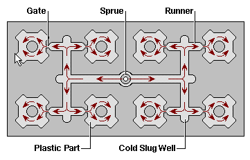
Cold Runner and Gate system
Overview: 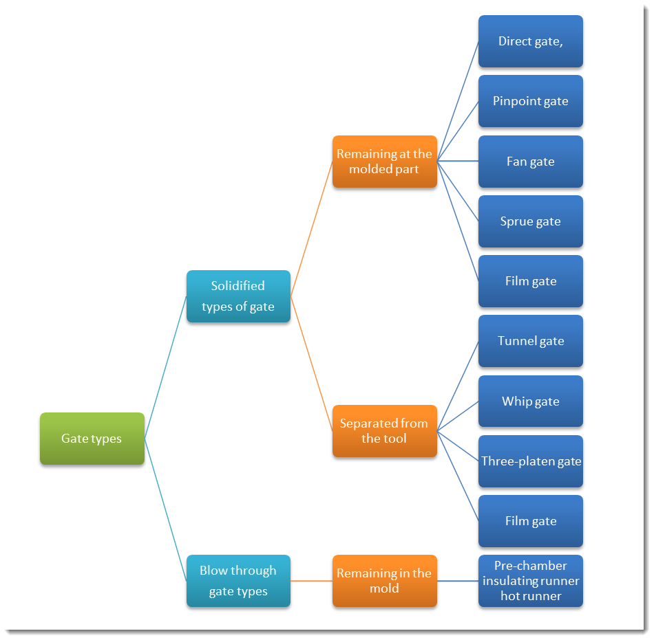
Function:
Cold-Runner Systems:
| 1 |
Sprue (canonical Shape for easy removal, 3-5 ° angle) ; connection between Nozzle and Runners; highly polished |
| 2 | Runners |
| 3 | Gates |

-
The gate channel serves to convey the melt coming from the nozzle of the injection molding machine to the cavity with:
| 1 |
the lowest possible pressure and heat loss, |
| 2 | in shortest possible time and |
| 3 | without thermal degradation. |
| 4 | In multi-cavity molds, the melt must be supplied to all gates uniformly |
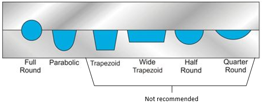
Gate types: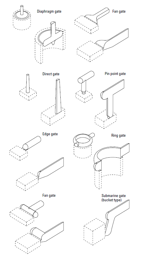
You are trying to load a table of an unknown type. Probably you did not activate the addon which is required to use this table type.
Risk:
- location of the gate is the weakest spot (apart from weld lines)
- not balanced filling
- Spiral effect: 11, 14, 19, 22 will be filled First and mayshow splays and Mold Deposits
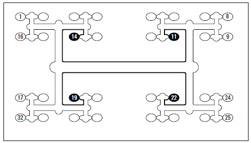
- wrong position of the gate on the molded part causes the formation of weld lines (meeting of melt fronts) and air traps
Design:
Key rules:
- runners should stay open until all cavities are properly filled and packed;
- runners should be large enough for adequate flow, minimum pressure loss and no overheating;
- runner size and length should be kept to the minimum consistent with previous guidelines.
-
gate should be located in the thickest wall of the part in order to make it possible to pack and compensate for shrinkage by using hold pressure
-
position the gate so that the air will be swept toward a parting line or ejector pin (where conventional vents can be located)
Runner balancing:
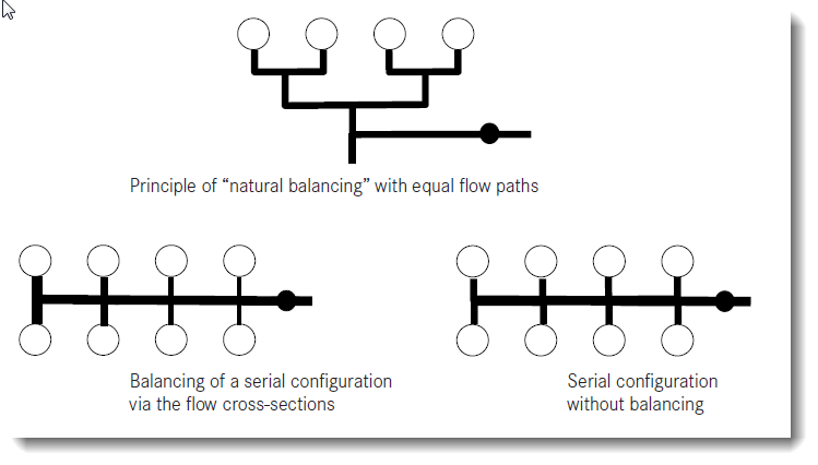
- the pressure loss in all gate paths is kept equally by “natural balancing” (equal cavities), but leads to longer gate paths, greater material losses and to larger molds
- Alternative different cross-sections , but fine-tuning needed.
Design rules for runner:
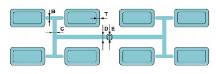
| Thickness cavity = T | |
| B | = T + 1mm |
| C | = T + 2mm |
| D | = T + 3mm |
| E | = T + 5mm |
| Nozzle diameter = 1 mm less than the diameter of the sprue |
- The minimum recommended runner diameter for most materials is 1.5 mm
- For most materials, the runner surface and sprue should be polished in the line of material flow.
- Cavities and cores should be polished in the line of draw unless an alternative finish has been specified.
- It is desirable to have multiple sprue pullers and ejection locations in extended runner systems.
- When designing hot runner systems, it is advisable to consult the suppliers for availability and recommendations for the correct manifold and drop
You are trying to load a table of an unknown type. Probably you did not activate the addon which is required to use this table type.
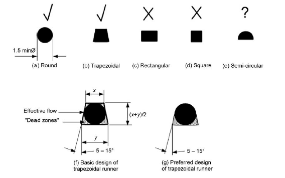
Gate design Rules:
-
gate cross-section is typically smaller than that of the runner and the part, so that the part can be easily de-gated
-
start with a fairly small gate since the gate can be increased with EDM using a slightly larger electrode if necessary
-
The gate length should be as short as possible to avoid an excessive pressure drop across the gate. A suitable gate length ranges from 1 mm to 1.5 mm (0.04–0.06 in)
- Resin suppliers provide usually info about gate design