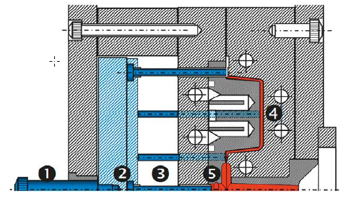
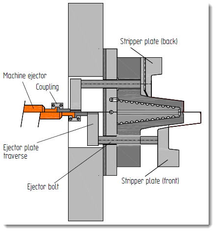
| 1 | ejector rod pushes against the machine frame |
| 2 | presses the ejector plates forward |
| 3 | These push the ejector pins against the part |
| 4 | part drops out |
| 5 | pressed against cold slug pocket which cause the runner also to drop |
Contents
Function:
The position of the ejector pins is regulated by the geometry of the molded part.
To prevent markings, it has to be ensured that the pins push against ribs, shoulders, and hidden molded part surfaces.
Risk:
- If the venting is inadequate there is a risk of filling problems of the cavities.
- Surface burns may also occur on the parts where the compressed air is trapped.
- reduce physical properties at weld lines
- Unsatisfactory design:Error
You are trying to load a table of an unknown type. Probably you did not activate the addon which is required to use this table type.
Design:
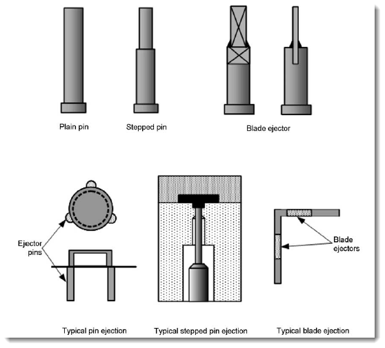
Ejector Pins:
- most common design
- Standard DIN 1530
- standard ejector pins with the largest possible diameter (about 20 mm) have to be chosen to avoid impressions
- Ejector pins can also provide ventilation (flattened areas)
- pins must be secured against rotation
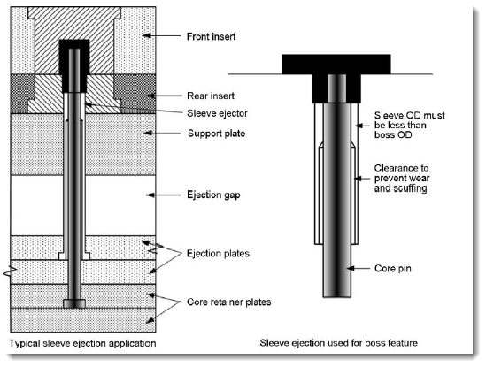
Sleeve ejector:
- for ring shaped parts -> tubular ejector
Ejector plate:
- for flat parts
- avoid deflecting by sufficient thickness
- Ejector plates of bigger molds are heated to avoid sticking of the ejector pins as a result of thermal expansion
-
demolding force is introduced over a large area
Mushroom Ejector:
- used for thin-walled packaging containers ( yogurt cups)
- located centrally on the molded part
- raises part about 10 – 15 mm, part is then ejected with air
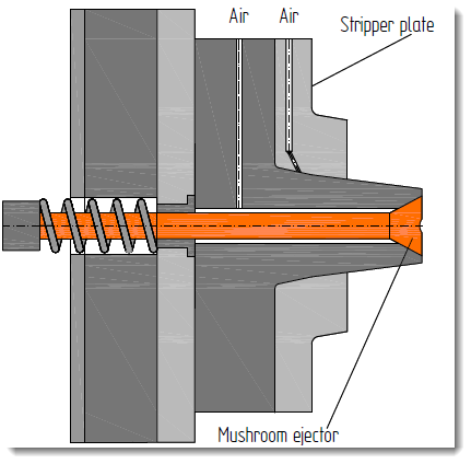
Air Ejector:
- nozzles and slots are attached supplied with compressed air,
- mainly used in molds for thin-walled parts.
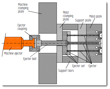
Actuation of ejector plates:
1. Ejecting by directly attached hydraulic cylinders,
2. Ejecting by a piston in the press table,
3. Ejecting using a stripper mechanism in the press

